These are reference ranges from existing materials. Maximum flow and highest purity may not coincide. Confirm the model, feed conditions, dew-point basis and optional configuration in the project datasheet.
ENGINEERING NOTES
Define the duty before selecting equipment.
The following establishes a technical discussion framework. Final performance, scope, certification and acceptance criteria are defined in the agreed technical specification.
01
Separation principle
Clean compressed air enters hollow-fibre membrane modules. Faster-permeating oxygen and water vapour pass through the membrane wall while nitrogen-rich gas exits the opposite end. With no adsorption-vessel cycling, the system supports fast starts and compact layouts.
Distinguish product gas from permeate.
Concept gas path. Project engineering defines vent handling, valve timing, sampling and safeguards; this is not a construction drawing.
ENGINEERING SCHEMATIC
Continuous membrane separation path
Fast gases permeate the hollow fibres while nitrogen-rich retentate continues to the process.
01Compressed airStable inlet
02Fine pretreatmentProtect modules
03Membrane modulesSelective permeation
04Fast-gas permeateOxygen & water vapour
05Nitrogen-rich productBuffered to process
02
Engineered configurations
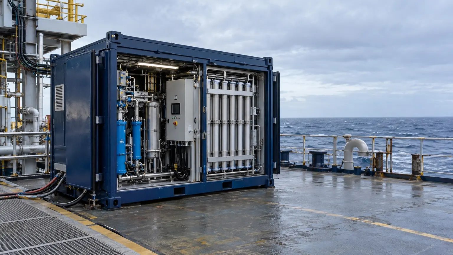
Systems can be configured as indoor cabinets, skids, containers or mobile packages, with instrumentation and controls selected for hazardous-area classification, ambient conditions, corrosion protection and project standards.
03
Membrane or PSA?
Selection should not be price-only. Higher purity often favours PSA, while rapid start, lower purity, low weight or limited space can favour membrane technology. Compare feed-air demand, energy, maintenance, environment and lifecycle cost.
04
Purity, recovery and feed-air demand
Membrane purity and recovery are linked. Raising purity normally reduces product recovery and increases feed air per unit of nitrogen, so purity should never be specified without flow and energy consequences.
05
Environment and module protection
High temperature, liquid water, oil aerosol and contaminants affect membrane performance. Offshore, desert and cold-climate packages require checks for inlet-temperature control, drainage, corrosion protection, insulation, heat tracing, ventilation and start-up procedure.
06
Mobile and container delivery
Mobile packages combine transport loads, lifting points, chassis, vibration, hose interfaces, quick connections, diesel or electric drive, earthing and hazardous-area requirements. Maximum practical integration should be tested before dispatch.
Image information
This image explains equipment configuration and engineering processes; it is not a customer-site or acceptance record.
EQUIPMENT & DELIVERY
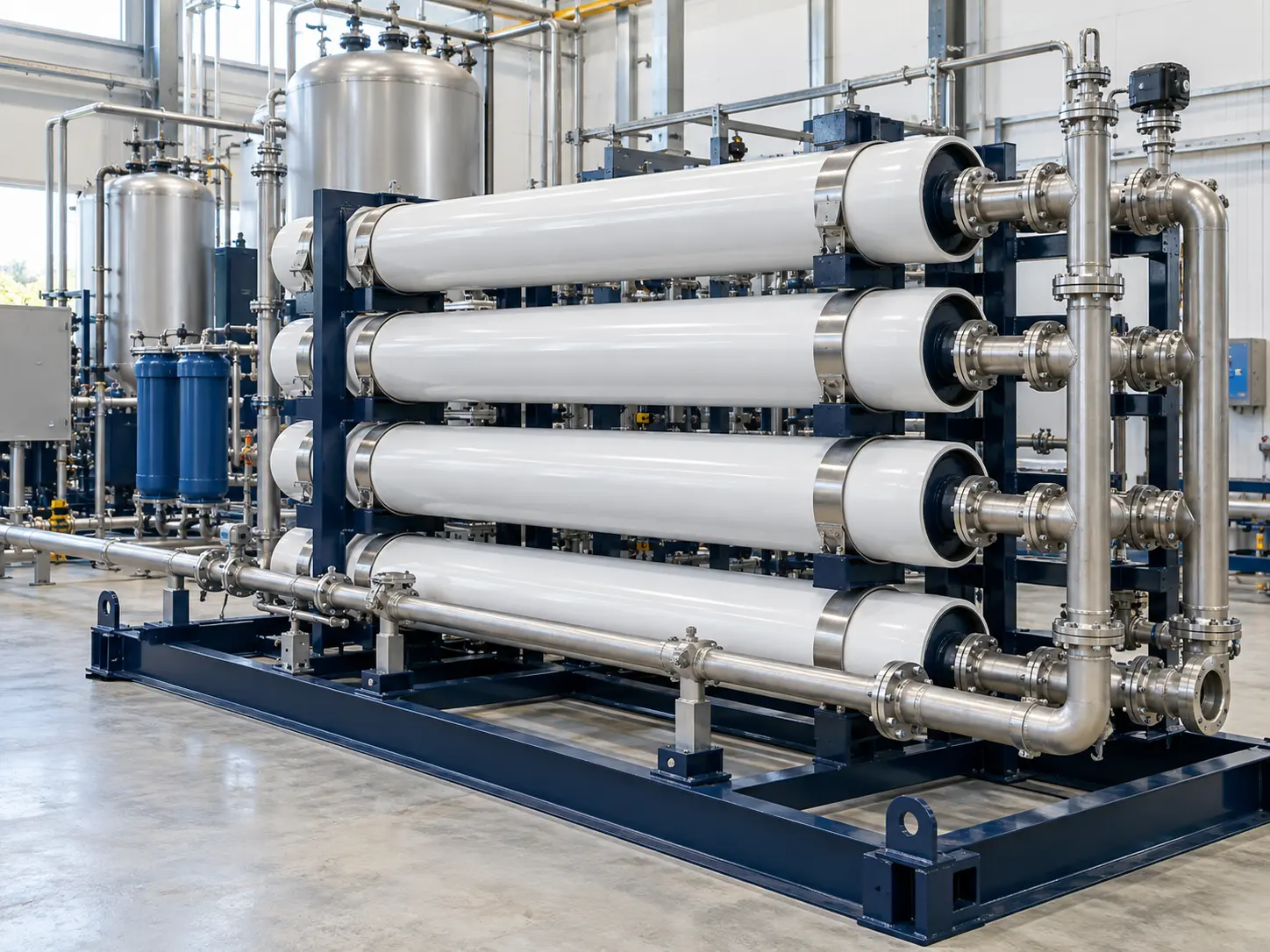
Select the membrane bank with its air treatment
Air enters the membrane bank. Faster-permeating gases leave on the permeate side, while nitrogen-rich gas exits the product side. Flow, purity, pressure and temperature interact; filtration and feed conditions must follow the membrane supplier’s data.
Image information
This image explains equipment configuration and engineering processes; it is not a customer-site or acceptance record.
EQUIPMENT & DELIVERY
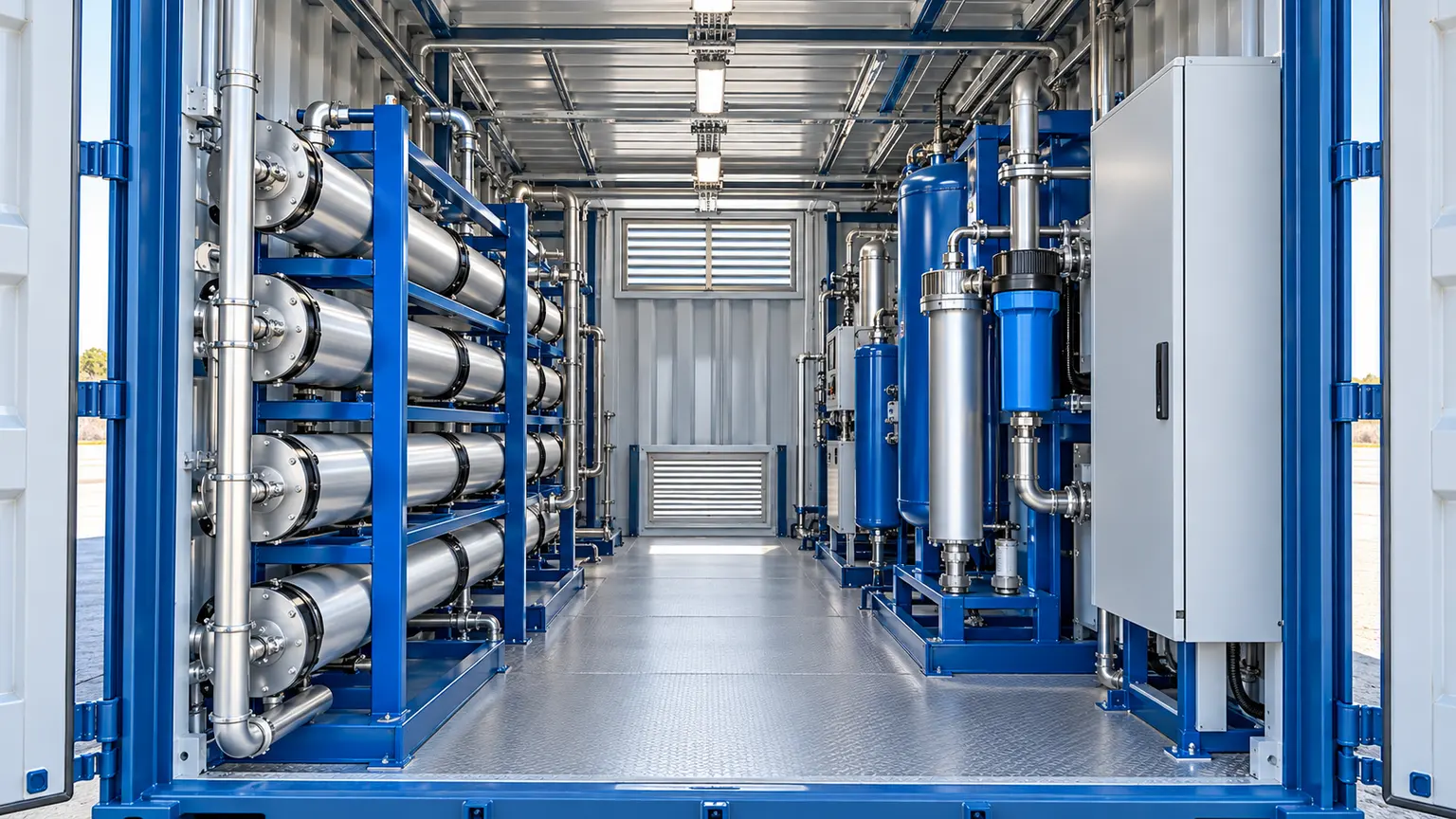
Leave room to maintain the package
A container combines equipment and interfaces in an engineered package. Check heat rejection, ventilation, drainage, noise, maintenance and electrical isolation. Transport dimensions and lifting arrangements require a separate review; this concept has no assumed dimensions.
Image information
This image explains equipment configuration and engineering processes; it is not a customer-site or acceptance record.
EQUIPMENT & DELIVERY
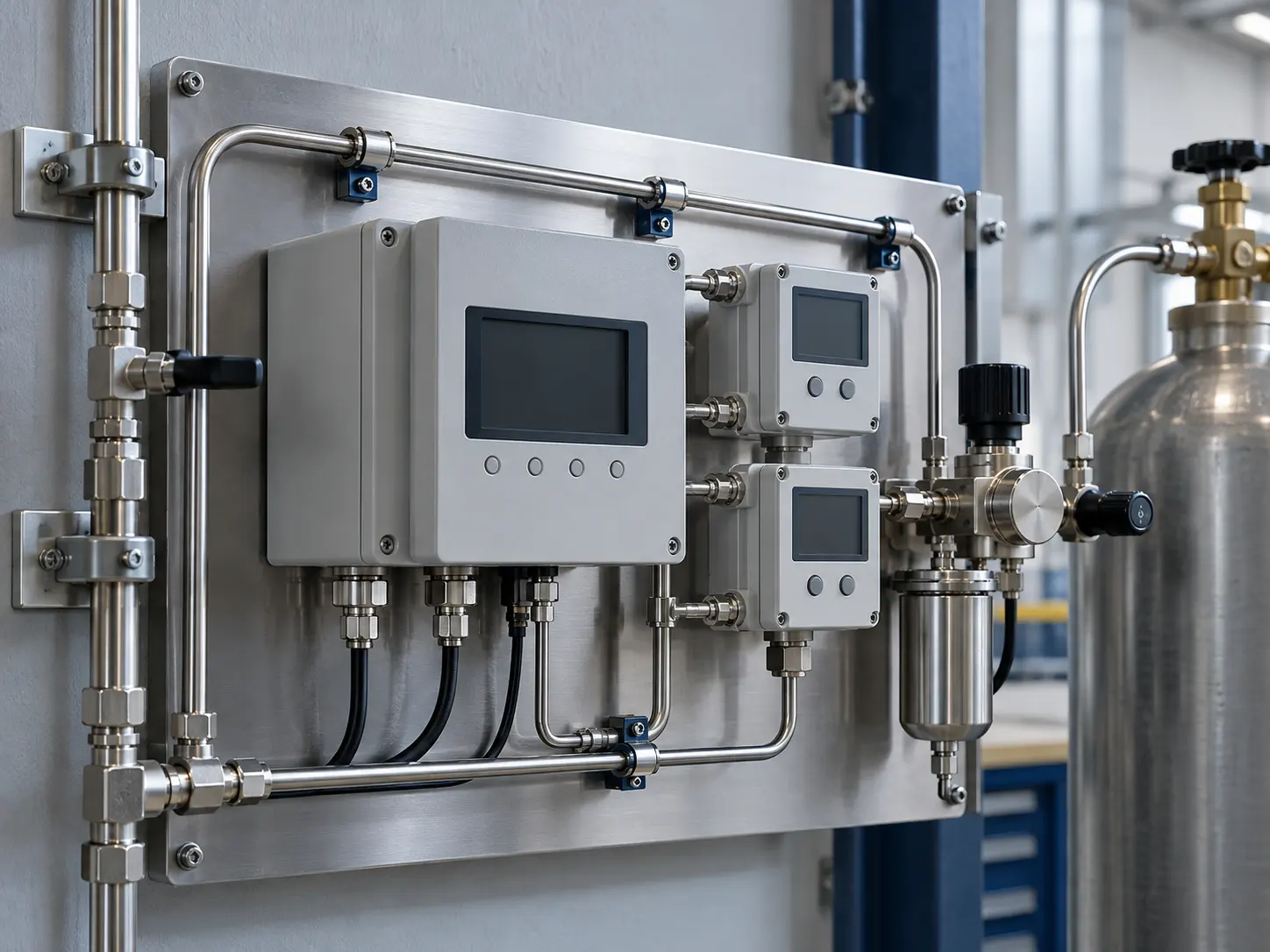
Measurement starts with the sampling point
Purity, residual oxygen and dew point are different specifications. Define the analyte, sampling location and pressure basis before choosing instruments, alarms and off-spec handling. The illustration explains the arrangement and contains no test readings.