Define the duty
Mine fire-prevention sizing must consider target volume, air leakage, injection method, oxygen-reduction time, line resistance and continuous supply period—not nameplate flow alone.
MINING
Focused on high flow, continuous duty, fire prevention, mobile deployment and remote-site support.
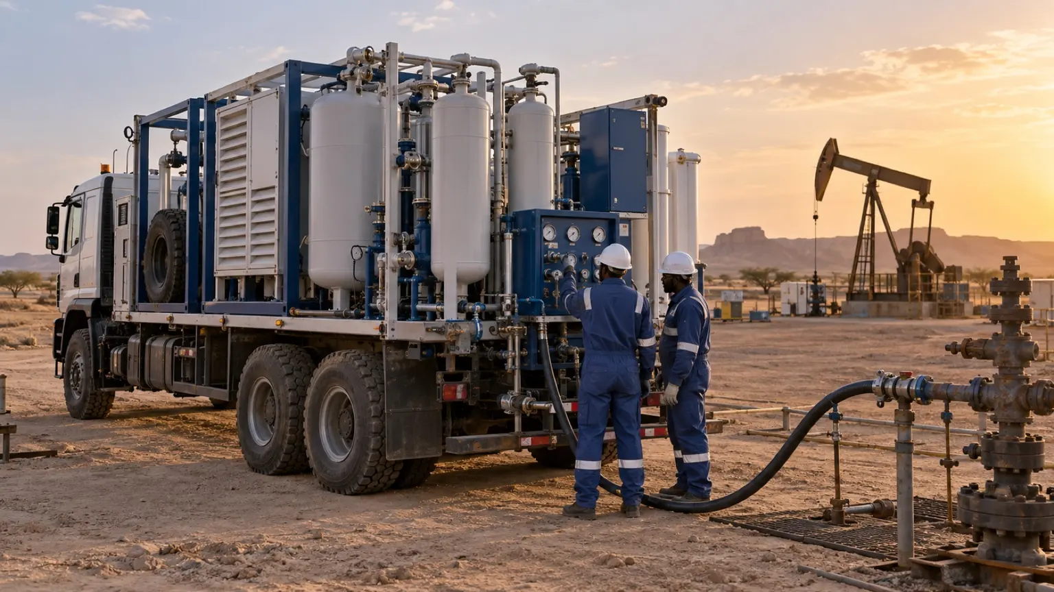
These are reference ranges from existing materials. Maximum flow and highest purity may not coincide. Confirm the model, feed conditions, dew-point basis and optional configuration in the project datasheet.
ENGINEERING NOTES
The following establishes a technical discussion framework. Final performance, scope, certification and acceptance criteria are defined in the agreed technical specification.
Mine fire-prevention sizing must consider target volume, air leakage, injection method, oxygen-reduction time, line resistance and continuous supply period—not nameplate flow alone.
ENGINEERING SCHEMATIC
The schematic clarifies the gas path and scope boundaries; final instruments, interlocks and layout follow the project specification.
Review dust, temperature, altitude, power quality, spare-parts access, operator capability and fault strategy. Parallel trains or mobile systems may be used where required.
Include flow, purity, pressure, endurance, alarms, interlocks and emergency changeover in acceptance, supported by operator start-up, inspection and fault-response training.
Long-term stable duty can favour an energy-optimised fixed plant. Changing work faces, emergency inerting or shared sites can favour vehicle or container packages. Compare relocation, connections, fuel, power and standby cost.
Diameter, length, bends, valves and elevation between the generator and injection point create pressure loss. The calculation should include surface plant, underground network and multi-point changeover so outlet capacity is not lost at the duty point.
Air intake, filtration, cooling, enclosure sealing and drainage must suit the mine environment. The maintenance plan should list critical consumables, mobile tools, remote diagnosis and backup nitrogen during faults.
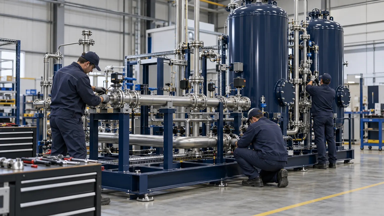
This image explains equipment configuration and engineering processes; it is not a customer-site or acceptance record.
EQUIPMENT & DELIVERY
Assembly follows controlled drawings and the equipment list. Review pipe supports, service access, electrical connections and instrumentation. Agree inspection items, test conditions and documents before manufacture. This manufacturing illustration is not evidence of a passed FAT.
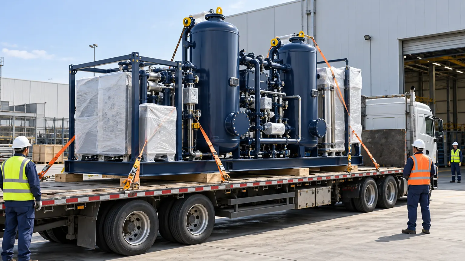
This image explains equipment configuration and engineering processes; it is not a customer-site or acceptance record.
EQUIPMENT & DELIVERY
Confirm the equipment list, preservation, lifting points, centre of gravity and transport limits before dispatch. The site prepares foundations, power, earthing, gas and drainage interfaces. Written responsibilities reduce rework. This image illustrates preparation, not a case shipment.
SYSTEM BOUNDARY
PAGE FAQ
Not always. Calculate from target volume, leakage, injection strategy and required time.
Compare available power, diesel logistics, emissions, ventilation, noise, maintenance and continuous-duty needs.
No. Include flow, pressure, dew point, endurance, alarms, interlocks and changeover logic.
CONTACT KEVIN
Send Kevin your application, location and the data you have. We will work through the next steps together.