Industrial Nitrogen System Design
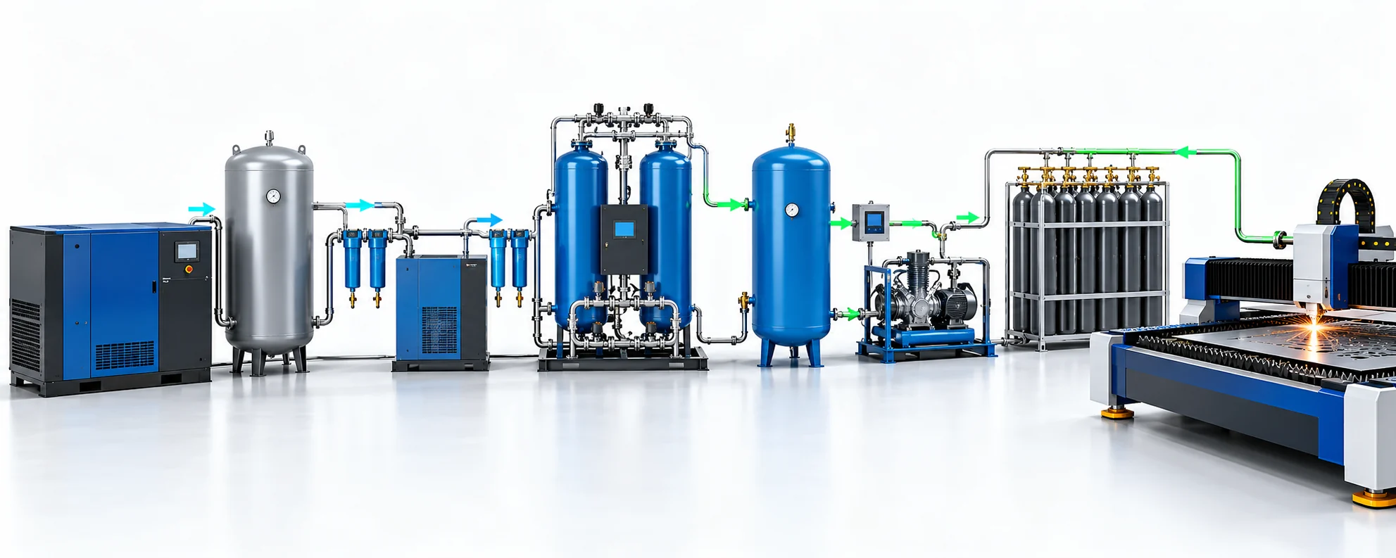
A nitrogen generator does not normally deliver gas at the same pressure as the compressed air entering it. Pressure is lost through air treatment, the separation module, buffer vessels, valves and distribution piping. If the process needs a higher pressure than the generator can maintain at its rated flow and purity, the project needs either a lower-loss distribution design, local storage, a booster—or a combination of them.
The Three Pressures Buyers Must Keep Separate
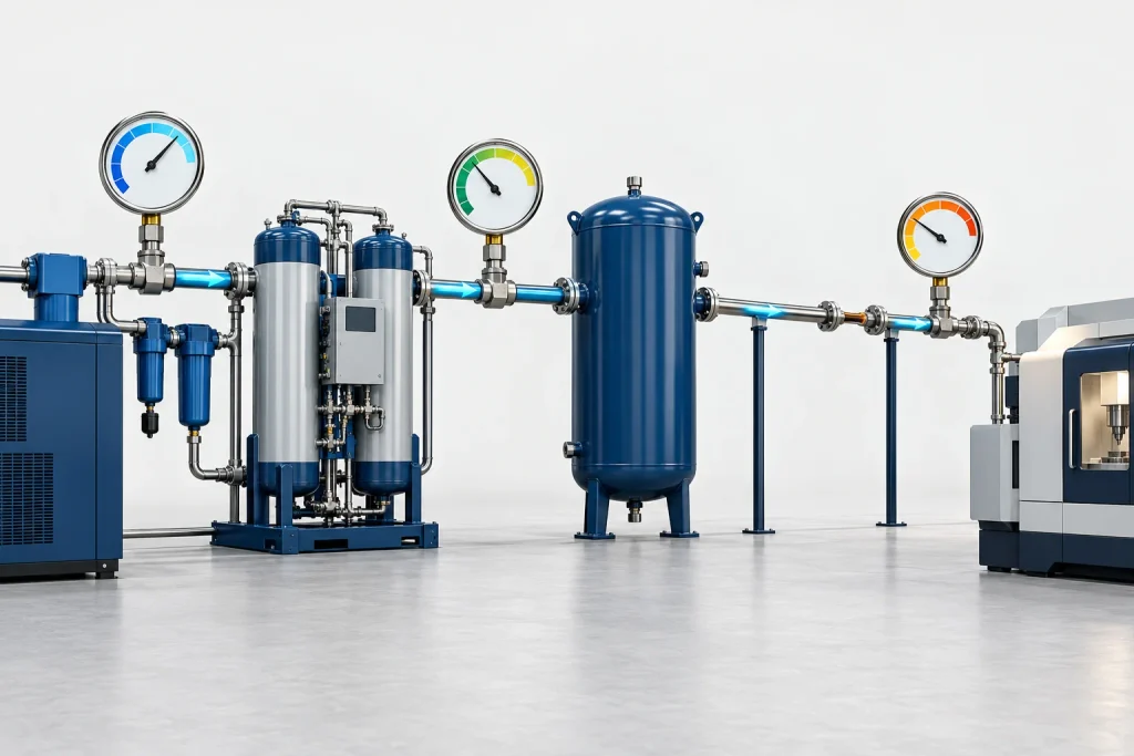
A pressure statement is incomplete unless it names the measurement point and operating condition. “We need 7 bar nitrogen” can mean 7 bar at the generator outlet, 7 bar at the process inlet during a steady load, or 7 bar during a short peak at the far end of the plant. Those are three different design duties.
| Pressure | Where it is measured | What affects it | Typical mistake |
|---|---|---|---|
| Compressed-air inlet pressure | At the nitrogen generator inlet after air treatment | Compressor set point, dryer and filter losses, plant-air demand | Using compressor discharge pressure instead of the pressure actually available at the generator |
| Generator outlet pressure | At the nitrogen outlet under a stated flow and purity | Generator design, inlet pressure, control valves, buffer arrangement and operating point | Assuming it equals inlet pressure |
| Point-of-use pressure | At the process connection during real demand | Pipe diameter and length, fittings, regulators, filters, elevation and peak flow | Checking only static pressure when production is idle |
The correct sequence is therefore: define the minimum dynamic pressure at the process, calculate distribution losses at normal and peak flow, then work backwards to the generator outlet and compressed-air inlet. Pressure is one input in the wider nitrogen generator sizing process; it cannot be selected independently of flow, purity and load profile.
Compressed-Air Inlet Pressure: Use the Pressure at the Generator
The generator sees the pressure remaining after the compressor, receiver, separator, dryer, filters and connecting pipe have done their work. A compressor set to 8 bar does not prove that 8 bar reaches the separation module. A loaded filter, an undersized dryer connection or a simultaneous plant-air peak can reduce the available pressure exactly when nitrogen demand is highest.
Manufacturers therefore publish a model-specific inlet operating range or reference condition. For example, one Parker twin-tower PSA range lists a recommended inlet pressure of 110 psig (7.6 bar), a permitted range of 80–140 psig (5.5–9.7 barg) and a listed pressure drop of 30 psid (2 bar). An Atlas Copco industrial range publishes reference inlet conditions around 7–7.5 barg while listing nitrogen outlet pressure at 6 barg. These are product-family examples—not universal NITRAISE ratings—but they demonstrate why an inlet figure cannot be copied into an outlet-pressure promise.
Two established suppliers publish different operating envelopes, and both separate inlet from outlet pressure. The RFQ should therefore state the lowest pressure available at the generator during simultaneous plant demand, not only the compressor nameplate pressure.
If the available inlet pressure falls below the selected model’s rated condition, the outcome depends on the equipment and control strategy: capacity may fall, outlet pressure may become unstable, or the unit may no longer hold the specified purity at the required flow. The vendor must confirm the complete operating envelope; a single catalogue point is not enough.
Published examples: Parker twin-tower nitrogen generator bulletin and Atlas Copco NGP industrial nitrogen generator data. Always use the selected model’s current approved data sheet.
Generator Outlet Pressure: State Flow and Purity with It
Generator outlet pressure must be stated at the agreed nitrogen flow, purity and inlet condition. The sentence “outlet pressure: 6 barg” is still incomplete if the buyer does not know whether that value applies at design flow, turndown, start-up or a brief no-flow condition.
The outlet buffer is part of this discussion. It does not create a higher pressure than the source, but it can reduce rapid pressure movement as twin PSA vessels switch and as downstream demand changes. Parker’s published NSP-080 information, for example, specifies a minimum buffer volume and warns that a smaller buffer can lead to lower outlet pressure and purity fluctuation. The exact vessel size remains model- and duty-specific.
Define at least four outlet conditions in a purchase specification:
- normal outlet pressure at normal flow and specified purity;
- minimum outlet pressure at peak flow;
- maximum allowable outlet pressure for downstream equipment;
- start-up and off-spec gas handling before nitrogen is released to the process.
The nitrogen generator working-principle guide explains why the separation module is only one part of the package. For pressure verification, instruments should distinguish generator inlet, nitrogen outlet, buffer pressure and the process connection rather than relying on one gauge.
Point-of-Use Pressure: Calculate the Loss at Peak Flow
The pressure that matters to production is the dynamic pressure at the consumer while gas is flowing. Long pipe runs, small bores, isolation valves, filters, regulators and flexible hoses all consume pressure. The loss rises sharply as flow increases. In a Compressed Air & Gas Institute example, a filter losing 4 psig at 350 cfm was shown losing approximately 16 psig when flow doubled to 700 cfm. Nitrogen piping must be calculated on its own gas conditions, but the example makes the practical point: a component that looks acceptable at average flow can dominate the loss during a peak.
A process needs at least 5.5 barg at the machine during a 60 Nm³/h peak. The proposed distribution line is estimated to lose 0.6 bar at that peak, the final regulator and filtration consume 0.3 bar, and the project reserves 0.2 bar for control margin.
Required upstream pressure = 5.5 + 0.6 + 0.3 + 0.2 = 6.6 barg.
If the selected generator can maintain only 6 barg at the specified purity and flow, the design is short by 0.6 bar. The first options to test are a larger pipe, fewer restrictions, a local receiver or a lower-loss final assembly. A booster is justified only if the required pressure still exceeds what the optimized low-pressure system can deliver.
This calculation should be repeated for normal flow and every credible peak. A static gauge reading taken while the machine is stopped cannot validate the duty. Record pressure at the generator and at the process simultaneously; the difference shows whether the constraint is generation or distribution.
Pressure-loss behaviour example: CAGI Compressed Air & Gas Handbook, Chapter 4. Use a qualified piping calculation for the actual nitrogen pressure, temperature, pipe material and fittings.
When Storage Solves the Peak—and When a Booster Is Required
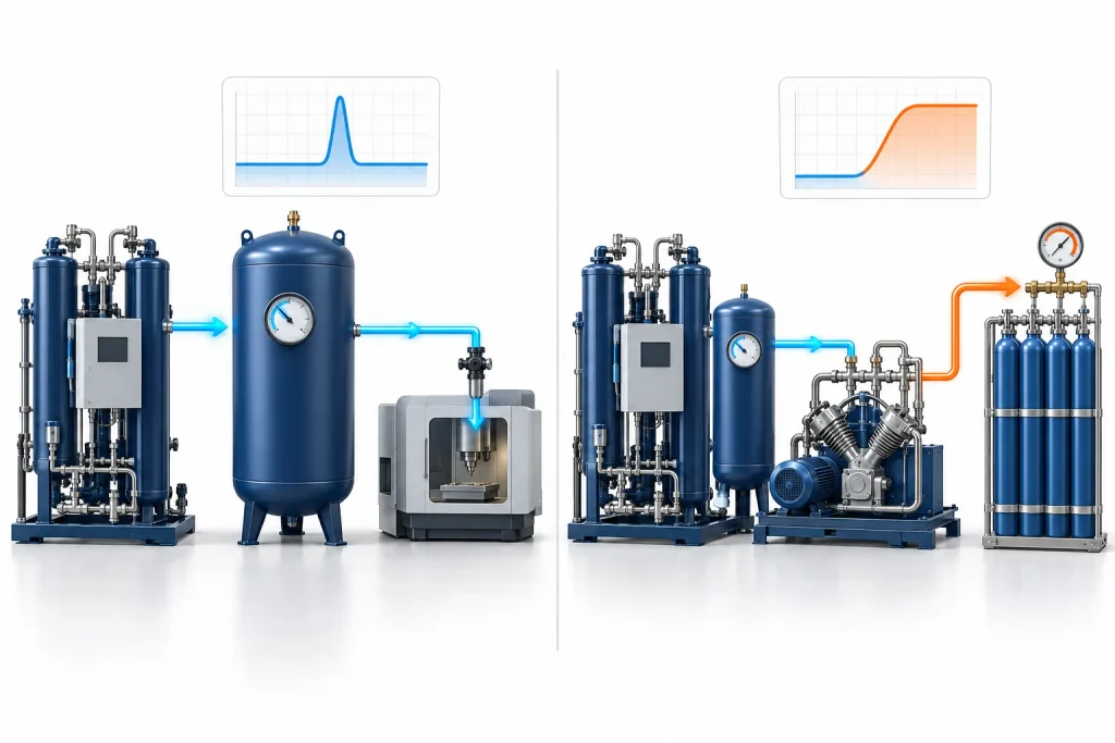
A receiver stores gas at the available pressure. It can cover a short flow peak, reduce rapid cycling and give controls time to respond, but it cannot raise nitrogen above its charging pressure. A booster adds pressure. It does not replace adequate generator capacity, and it should not be used to hide avoidable losses in undersized piping.
| Observed problem | Likely engineering response | What not to assume |
|---|---|---|
| Short flow peak at the same pressure, followed by enough recovery time | Evaluate local receiver volume and recharge time | A receiver can cover an unlimited or continuous deficit |
| Sustained demand exceeds generator capacity | Increase generation capacity, add modular capacity or reduce demand | A larger vessel creates more nitrogen |
| Process pressure remains above generator capability after distribution is optimized | Evaluate a correctly sized nitrogen booster and high-pressure storage | Increasing compressed-air inlet beyond the model limit is acceptable |
| Large intermittent demand with long idle periods | Evaluate booster plus storage, with verified recharge time and duty cycle | Average hourly flow alone sizes the booster |
| Pressure collapses only at the far end of a small or restrictive line | Correct piping, valves, filters or final regulation first | A booster is the first remedy for every low-pressure complaint |
A documented short-peak sizing example
CAGI presents a receiver-sizing example for an intermittent event requiring 62 cfm for 15 seconds, with receiver pressure falling from 100 psig to a critical 85 psig before recharge. The calculation gives about 112 gallons, so the next standard 120-gallon receiver is selected. That is a compressed-air example, not a nitrogen-generator prescription, but it shows the information a real peak calculation needs: flow, duration, initial pressure, minimum usable pressure and time between events.
For nitrogen service, the same conservation logic is used with the actual gas conditions, allowable pressure band, purity and local vessel code. If the process repeats before the receiver has recovered, the supposed “short peak” becomes a generation or booster duty.
A real high-pressure storage case
At Concept Metal Products, Atlas Copco documents an on-site system producing 38 Nm³/h at 99.99% nitrogen purity, with a compressor, generator, receivers, booster, dryers, filters and a high-pressure bottle bank. Storage was first installed at 240 m³ and later expanded to 480 m³. The site could fill storage overnight on a lower electricity tariff and draw from it during production. This is a clear case where storage did more than smooth seconds of demand: the complete operating schedule, storage capacity and refill window were designed together.
The generator flow alone did not describe the solution. High-pressure storage shifted production in time and supported the plant’s demand profile. A similar concept is useful only when the refill period, booster duty, vessel capacity and usable pressure band are all checked.
Booster Pressure Is Only Half the Specification
A booster selection also needs suction pressure, discharge pressure, gas flow, peak duration, frequency, ambient conditions and permitted cycling. Compression ratio and duty cycle affect temperature, maintenance interval and control philosophy. The upstream buffer must keep the booster from starving; the downstream storage and regulator must keep the process from forcing rapid starts and stops.
Two published laser-cutting projects show why the application name alone cannot set pressure:
| Published project | Documented pressure arrangement | Problem addressed |
|---|---|---|
| Transerve-JHT laser cutting | On-site nitrogen package with booster to a maximum of 40 bar | Supplied nitrogen for cutting approximately 0.5–4 mm material while avoiding reliance on delivered liquid nitrogen |
| Constant Group metal fabrication | 38 Nm³/h, 99.99% system with booster rated to 300 barg and 240 Nm³ storage | Supported continuous 4 mm cutting and a documented intermittent scenario for 12 mm cutting |
Both projects are described as laser-cutting nitrogen systems, yet one uses up to 40 bar and the other includes 300-bar compression and storage. Material thickness, machine requirement, consumption pattern, storage strategy and package design—not the label “laser cutting”—determined the pressure solution.
Controls must define what happens when storage reaches its upper set point, suction pressure falls, nitrogen is off specification, a high-temperature alarm occurs or demand exceeds the intended duty. The correct sequence may unload, stop, recycle, isolate or prevent gas release to the process. It should be agreed before fabrication, not improvised during commissioning.
Project evidence: Concept Metal Products case study, Transerve-JHT case study and Constant Group case study. Values describe those installed projects only.
High-Pressure Safety and the Equipment Boundary
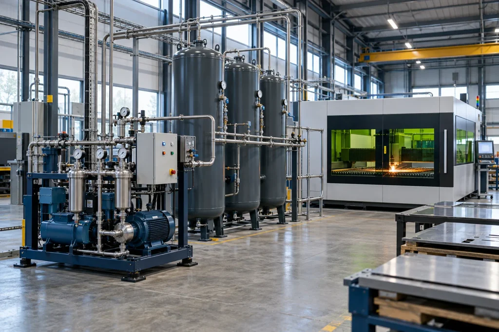
High-pressure nitrogen is not simply a low-pressure generator with a stronger hose. The project boundary must identify which party supplies the booster, suction buffer, aftercooling, separators or drains where applicable, high-pressure receiver or cylinder bank, relief devices, isolation, instrumentation, interconnecting pipework and commissioning.
Keep four pressure terms distinct:
- normal operating pressure—the intended steady operating value;
- maximum operating pressure—the highest value expected in the control range;
- design pressure—the pressure used with the applicable code and design temperature to design the component;
- relief set pressure—selected and verified under the governing code and protected-equipment limits.
Nitrogen can create an oxygen-deficient atmosphere, and stored high-pressure gas contains substantial energy. Vessel design, relief, ventilation, access control, inspection and operating procedures must be completed by qualified parties under the rules that apply at the installation location. This article is a selection guide, not a pressure-system design approval.
For United States installations, OSHA 29 CFR 1910.101 addresses inspection and handling of compressed-gas cylinders and incorporates relevant Compressed Gas Association requirements. CAGI also states that receivers should comply with applicable ASME, federal, state and local requirements. Other countries and industries have their own governing codes; the RFQ must name the jurisdiction rather than assuming one global rule.
Safety references: OSHA 29 CFR 1910.101 — Compressed gases and the CAGI Compressed Air & Gas Handbook. The project engineer must identify the current local requirements.
RFQ Pressure Checklist
Send pressure information as an operating profile, not a single number. A useful RFQ includes:
- pressure available at the generator inlet: normal, minimum and maximum;
- the exact inlet measurement point and simultaneous plant-air loads;
- required pressure at each point of use: minimum, normal and maximum;
- nitrogen flow and purity required at each pressure condition;
- peak flow, peak duration, frequency and time available for recovery;
- distance, elevation, pipe size, material, fittings, filters and regulators between generator and process;
- existing receiver or cylinder-bank volume, pressure rating and usable pressure band;
- whether booster and high-pressure storage are inside the supplier’s battery limit;
- required operating philosophy for off-spec gas, low suction pressure, high temperature and full storage;
- site jurisdiction, vessel code, hazardous-area classification, ambient range and utilities.
Add a demand timeline where possible. A table showing flow and pressure by minute—or a machine cycle file—is more useful than “average consumption.” Combine it with the defined nitrogen purity requirement; pressure, flow and purity must be guaranteed at the same operating point. For the rest of the enquiry, use the nitrogen generator RFQ checklist.
Frequently Asked Questions
What inlet pressure does a nitrogen generator need?
It depends on the selected generator. Use the manufacturer’s minimum, reference and maximum inlet conditions, then verify the pressure actually available after dryers, filters and piping during simultaneous plant demand. Do not use compressor discharge pressure as a substitute.
What outlet pressure can a nitrogen generator provide?
Outlet pressure is model-specific and must be stated with flow, purity and inlet pressure. It is normally lower than the compressed-air inlet because the treatment and separation system consume pressure.
Can a nitrogen receiver increase pressure?
No. A receiver stores nitrogen at the pressure supplied to it. It can cover a short peak and stabilize demand, but it cannot raise gas above its charging pressure.
Do I need a nitrogen booster?
A booster is normally evaluated when the process needs a pressure above the generator’s sustainable outlet pressure after avoidable distribution losses have been corrected. The decision also depends on peak duration, storage strategy, recharge time and duty cycle.
Why does nitrogen pressure fall when production starts?
Common causes include a demand peak above available generation, an undersized or restrictive distribution line, loaded filters, a regulator with inadequate flow capacity, insufficient local storage, low generator inlet pressure or unsuitable booster control. Compare simultaneous readings at the generator and process to locate the loss.
Define the Pressure Duty Before Selecting Hardware
To review a pressure requirement, send the minimum process pressure, normal and peak flow, peak duration, required purity, generator-to-process line details, existing storage and available compressed-air pressure. NITRAISE can then separate generation, distribution, storage and booster duties and define a package boundary that suppliers can quote consistently.
About the author: Henry Xu
Henry Xu is the founder of NITRAISE and a senior industrial equipment engineer with 18 years in nitrogen equipment research, development and production.