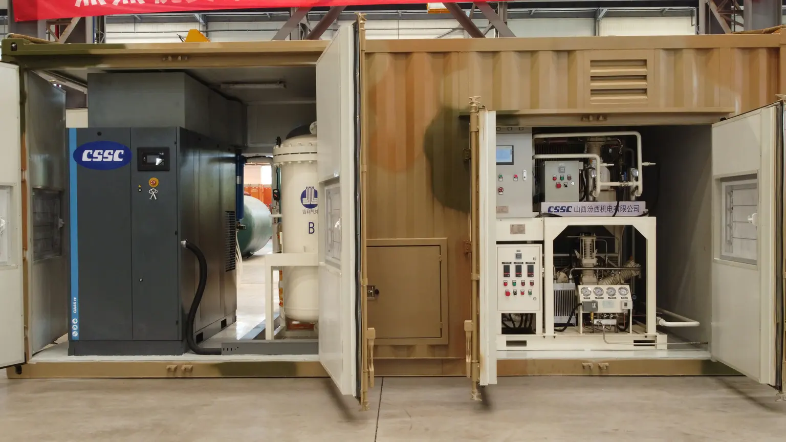
Start with the process requirement
Average and peak flow, minimum purity, outlet pressure, dew point, operating hours and the consequence of losing supply determine technology and system size.
NITROGEN GENERATION SYSTEMS
Choose by technology and package format: PSA, membrane, high-flow, skid and container—with selection data and system boundaries on every page.
Compare PSA and membrane at the same duty.
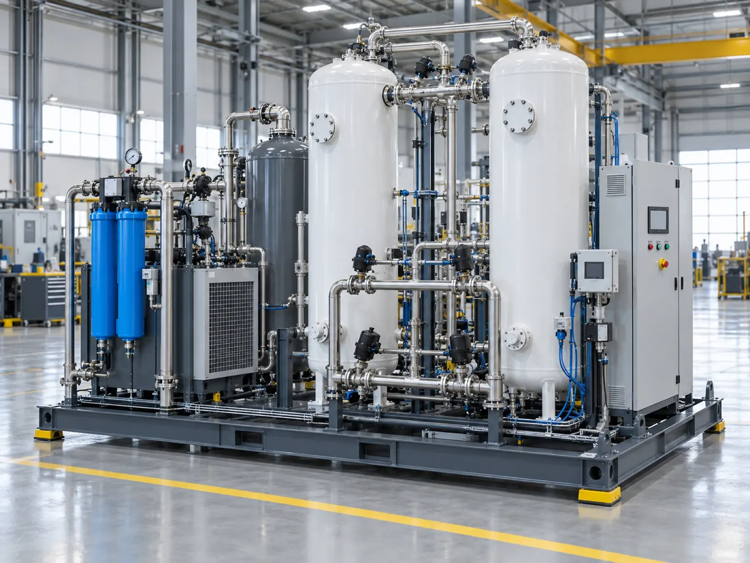
Engineered for continuous industrial demand, with the complete system configured around flow, purity, pressure and load profile.
↗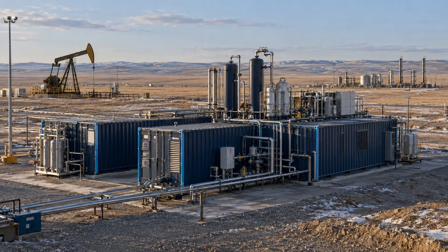
Compact and fast-starting systems for oil and gas, offshore, mobile and selected low-to-medium purity duties.
↗Purity, pressure and high flow are configuration requirements that can overlap. Maximum values are not assumed to occur together.
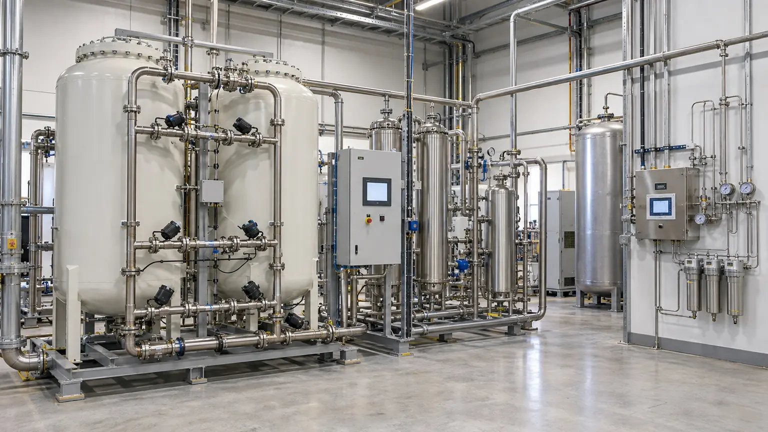
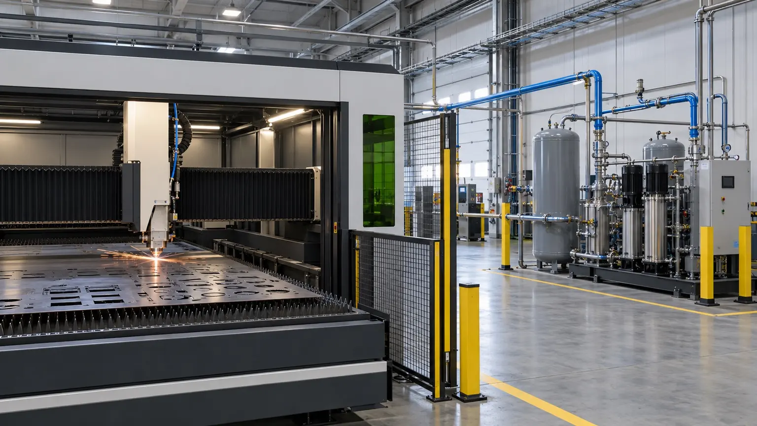
Generation, purification, analysis, storage and off-spec handling configured from the process residual-oxygen limit.
↗
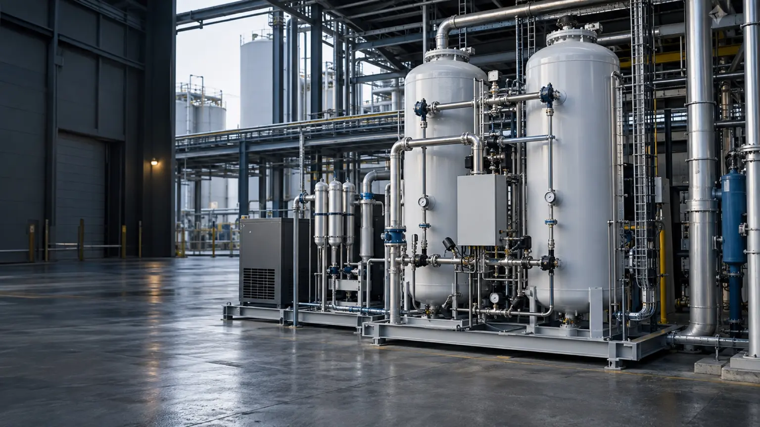
Generator, booster, storage and pressure control engineered as one system against continuous flow and peak cycles.
↗
System-level engineering for mining, marine, chemical, new-energy and large continuous processes.
↗Skids and containers define integration and transport, rather than a separate separation technology.
Average and peak flow, minimum purity, outlet pressure, dew point, operating hours and the consequence of losing supply determine technology and system size.
Compression, treatment, storage, boosting, analysis, controls, backup gas and installation interfaces must share one comparison boundary before equipment prices are meaningful.
Define reference conditions, instrument accuracy, sampling point, stabilisation, test duration and off-spec handling so promised performance can be verified on site.
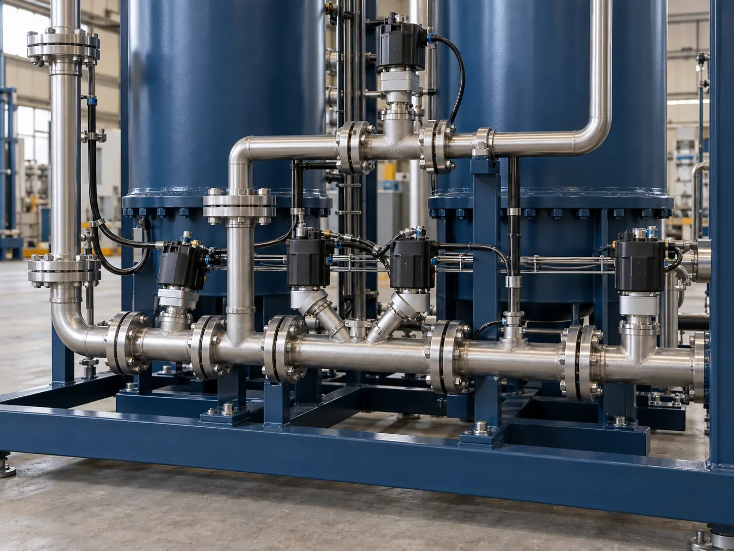
This image explains equipment configuration and engineering processes; it is not a customer-site or acceptance record.
EQUIPMENT & DELIVERY
One tower adsorbs while the other regenerates. Valves sequence feed, pressure equalisation, delivery and exhaust. Buffering and off-spec handling must be assessed separately from the process demand, with access and spares planned for the valves.
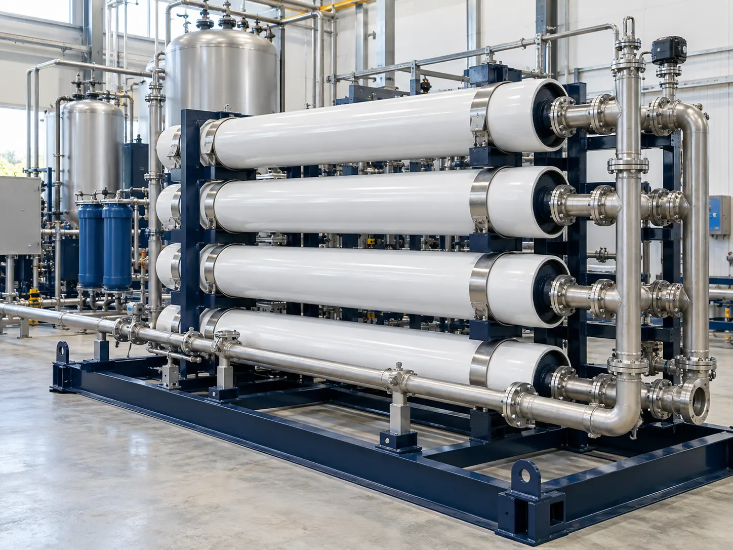
This image explains equipment configuration and engineering processes; it is not a customer-site or acceptance record.
EQUIPMENT & DELIVERY
Air enters the membrane bank. Faster-permeating gases leave on the permeate side, while nitrogen-rich gas exits the product side. Flow, purity, pressure and temperature interact; filtration and feed conditions must follow the membrane supplier’s data.
CONTACT KEVIN
Send Kevin your application, location and the data you have. We will work through the next steps together.