Work back from the cutting process
Material, thickness, nozzle and cutting speed change pressure and consumption. Use actual programs to determine peaks and simultaneity rather than one average figure.
LASER CUTTING
High-pressure nitrogen configured around laser power, nozzle, material, cutting cycle, pressure and peak flow.
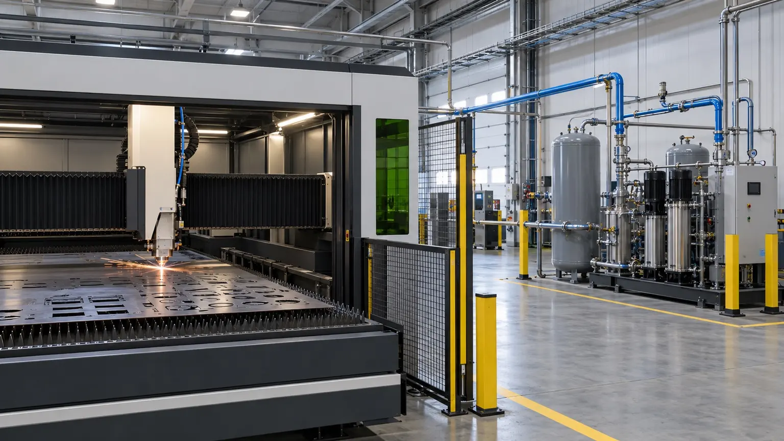
These are reference ranges from existing materials. Maximum flow and highest purity may not coincide. Confirm the model, feed conditions, dew-point basis and optional configuration in the project datasheet.
ENGINEERING NOTES
The following establishes a technical discussion framework. Final performance, scope, certification and acceptance criteria are defined in the agreed technical specification.
Material, thickness, nozzle and cutting speed change pressure and consumption. Use actual programs to determine peaks and simultaneity rather than one average figure.
ENGINEERING SCHEMATIC
The diagram shows calculation and supply logic; it does not replace the project P&ID, HAZOP or machine-interface document.
Scope may include compression, generation, buffering, boosting, high-pressure storage, filtration, regulation and point-of-use monitoring. Every interface must meet machine and process requirements.
Edge colour, oxidation and stability should be accepted together with gas analysis, pressure trends and cutting trials.
Ambient temperature, altitude, dust or cleanliness, power, cooling, compressed air, space, logistics and local codes can change capacity, layout and scope.
List compression and treatment, generation or membranes, purification, boosting, storage, analysis, venting, controls, communications, piping and installation interfaces rather than comparing generator price alone.
Maintain continuity from factory testing and preservation through arrival inspection, SAT, training and operating trends. Contract and acceptance records govern final performance, responsibility and warranty.
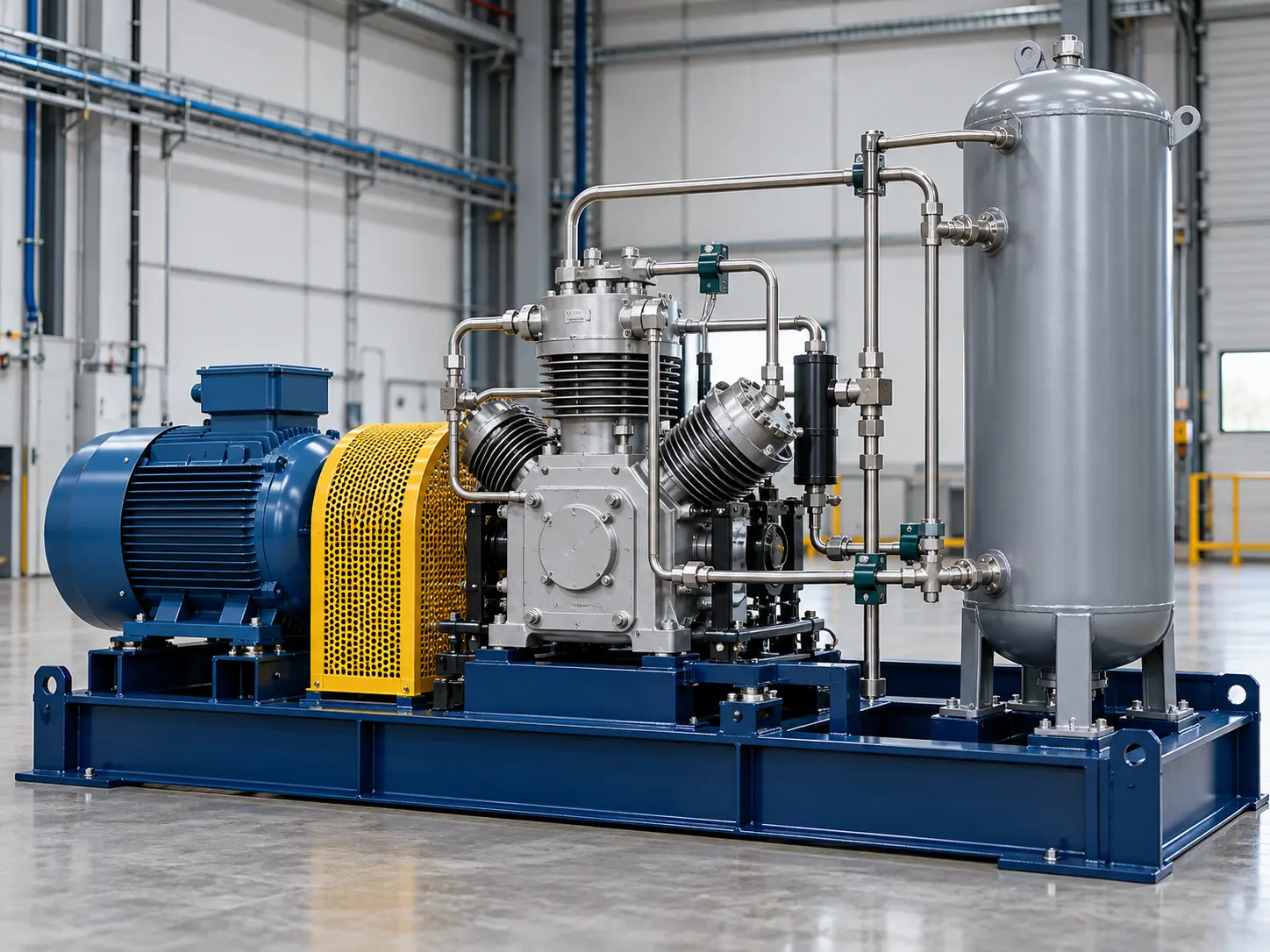
This image explains equipment configuration and engineering processes; it is not a customer-site or acceptance record.
EQUIPMENT & DELIVERY
The generator and booster have separate performance limits. Line losses and peaks affect pressure at the user. Low-pressure buffering, high-pressure storage, regulation and protection must be checked as one system, using the selected booster curve and project data.
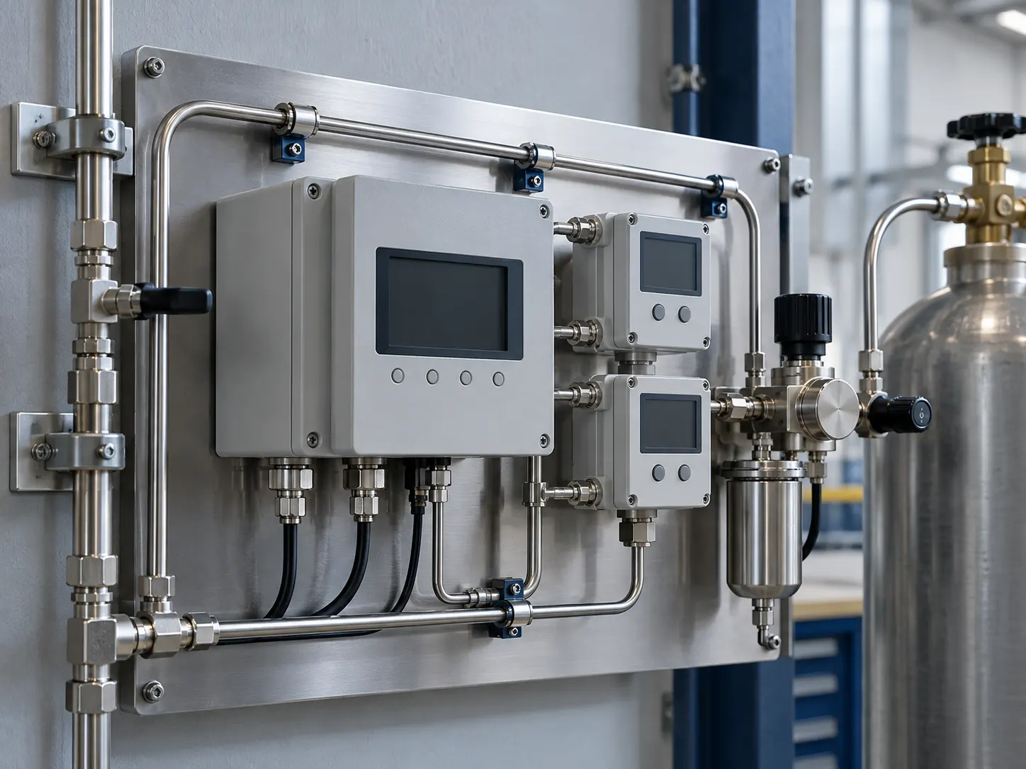
This image explains equipment configuration and engineering processes; it is not a customer-site or acceptance record.
EQUIPMENT & DELIVERY
Purity, residual oxygen and dew point are different specifications. Define the analyte, sampling location and pressure basis before choosing instruments, alarms and off-spec handling. The illustration explains the arrangement and contains no test readings.
SYSTEM BOUNDARY
PAGE FAQ
Provide the process, average and peak flow, minimum purity, pressure, dew point, hours, environment, standards and target production date.
Standard modules may be the foundation, but train count, storage, treatment, controls and interfaces must be checked against the actual duty and site.
Write reference conditions, measurement method, sampling point, stabilisation, test duration, off-spec handling and responsibilities into the technical agreement.
CONTACT KEVIN
Send Kevin your application, location and the data you have. We will work through the next steps together.