Demand calculation
Initial purge demand differs from normal blanketing demand. The first depends on volume, displacement efficiency and oxygen target; the second on level changes, thermal breathing, leakage and valve operation.
APPLICATION
Continuous and peak demand calculated from tank volume, breathing losses, media and oxygen target.
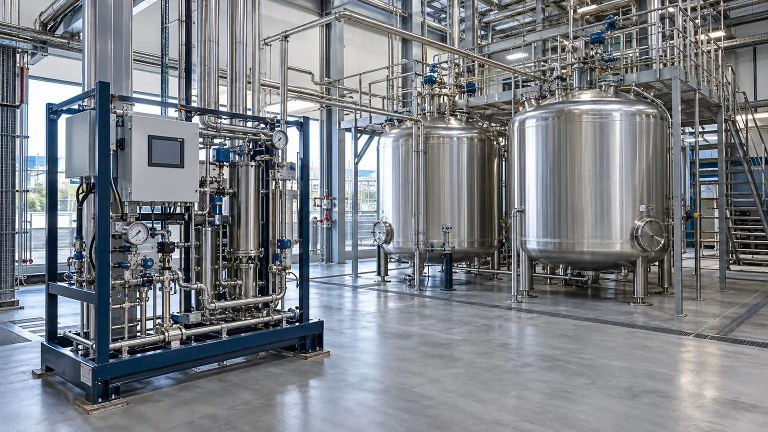
These are reference ranges from existing materials. Maximum flow and highest purity may not coincide. Confirm the model, feed conditions, dew-point basis and optional configuration in the project datasheet.
ENGINEERING NOTES
The following establishes a technical discussion framework. Final performance, scope, certification and acceptance criteria are defined in the agreed technical specification.
Initial purge demand differs from normal blanketing demand. The first depends on volume, displacement efficiency and oxygen target; the second on level changes, thermal breathing, leakage and valve operation.
ENGINEERING SCHEMATIC
The diagram shows calculation and supply logic; it does not replace the project P&ID, HAZOP or machine-interface document.
Typical scope includes low-pressure regulation, buffer storage, tank-top pressure control, oxygen analysis, low-pressure alarm and backup connection. Relief and interlock design remains process-specific.
Provide tank count and volume, media, transfer rate, oxygen target, blanketing pressure, simultaneity, line length, ambient temperature and applicable code.
Define whether dilution, pressure cycling or displacement is used. Initial and target oxygen, mixing behaviour and volume determine the required exchanges, with allowance for leakage, dead zones and operation.
Product transfer, day-night temperature swing, vapour condensation, valve movement and simultaneous tank breathing create peaks. Regulators, headers and buffers should be checked dynamically.
Generator pressure is normally buffered and reduced before the tank farm. Overpressure, backflow and misconnection must be prevented, while the process team confirms vent, relief and emergency isolation.
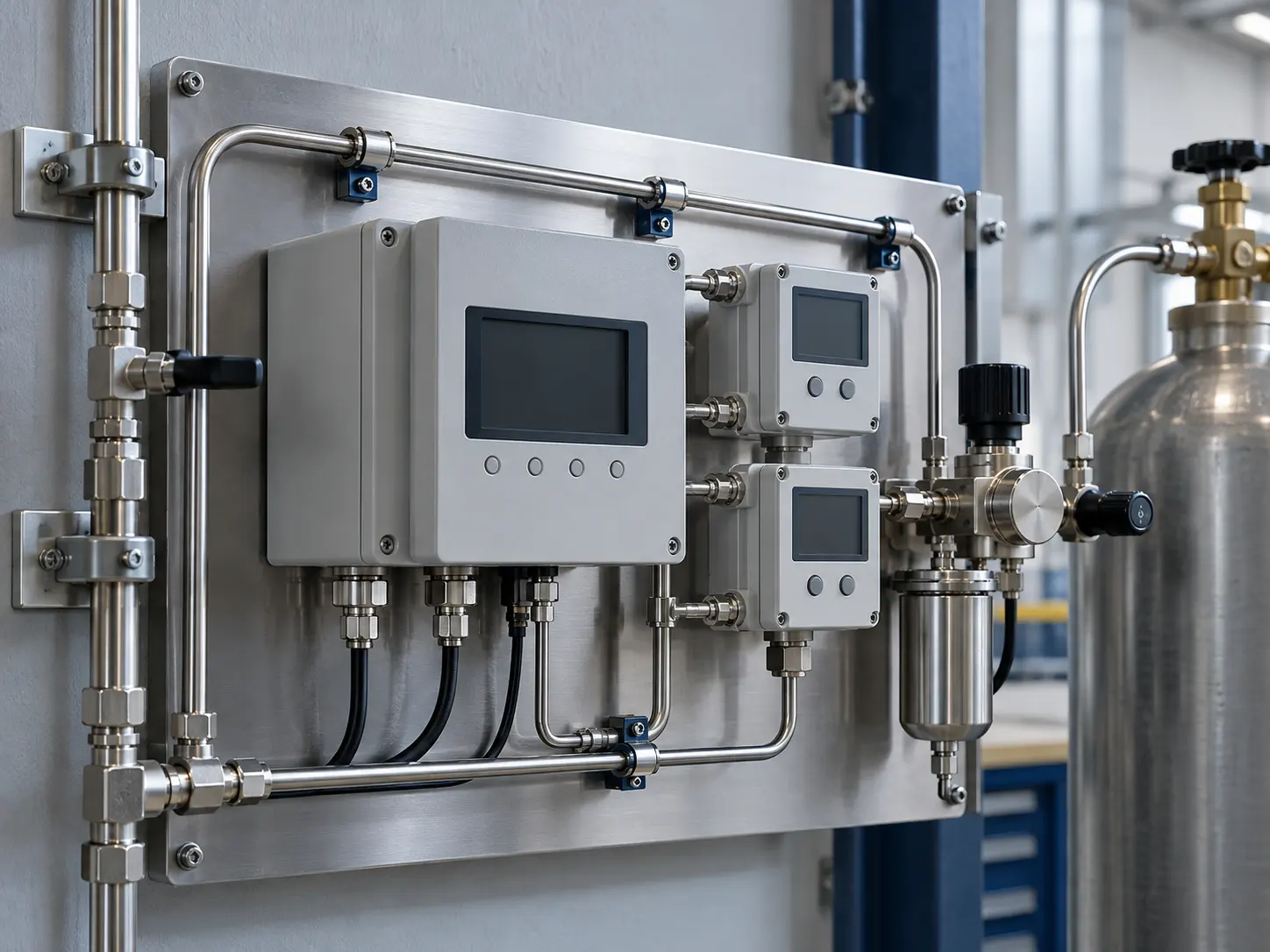
This image explains equipment configuration and engineering processes; it is not a customer-site or acceptance record.
EQUIPMENT & DELIVERY
Purity, residual oxygen and dew point are different specifications. Define the analyte, sampling location and pressure basis before choosing instruments, alarms and off-spec handling. The illustration explains the arrangement and contains no test readings.
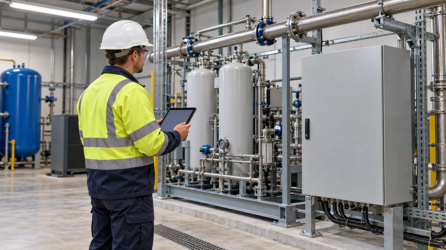
This image explains equipment configuration and engineering processes; it is not a customer-site or acceptance record.
EQUIPMENT & DELIVERY
After connection, check instruments, alarms, gas quality, pressure and off-spec handling under the agreed test plan, then complete training and handover. Acceptance depends on actual records; the screen shown here contains no performance data.
SYSTEM BOUNDARY
PAGE FAQ
Yes, after checking the initial high-flow duty, storage, available time and normal low-load turndown.
The tank and process design define it from allowable pressure, vent valves and media requirements.
It depends on risk and acceptance; critical inerting duties commonly justify defined sampling and analysis.
CONTACT KEVIN
Send Kevin your application, location and the data you have. We will work through the next steps together.