The pressure profile drives configuration
Maximum pressure alone is not enough. Provide continuous flow at each pressure level, peak duration, cycling frequency, allowable drop and recovery time.
HIGH-PRESSURE NITROGEN
Generator, booster, storage and pressure control engineered as one system against continuous flow and peak cycles.
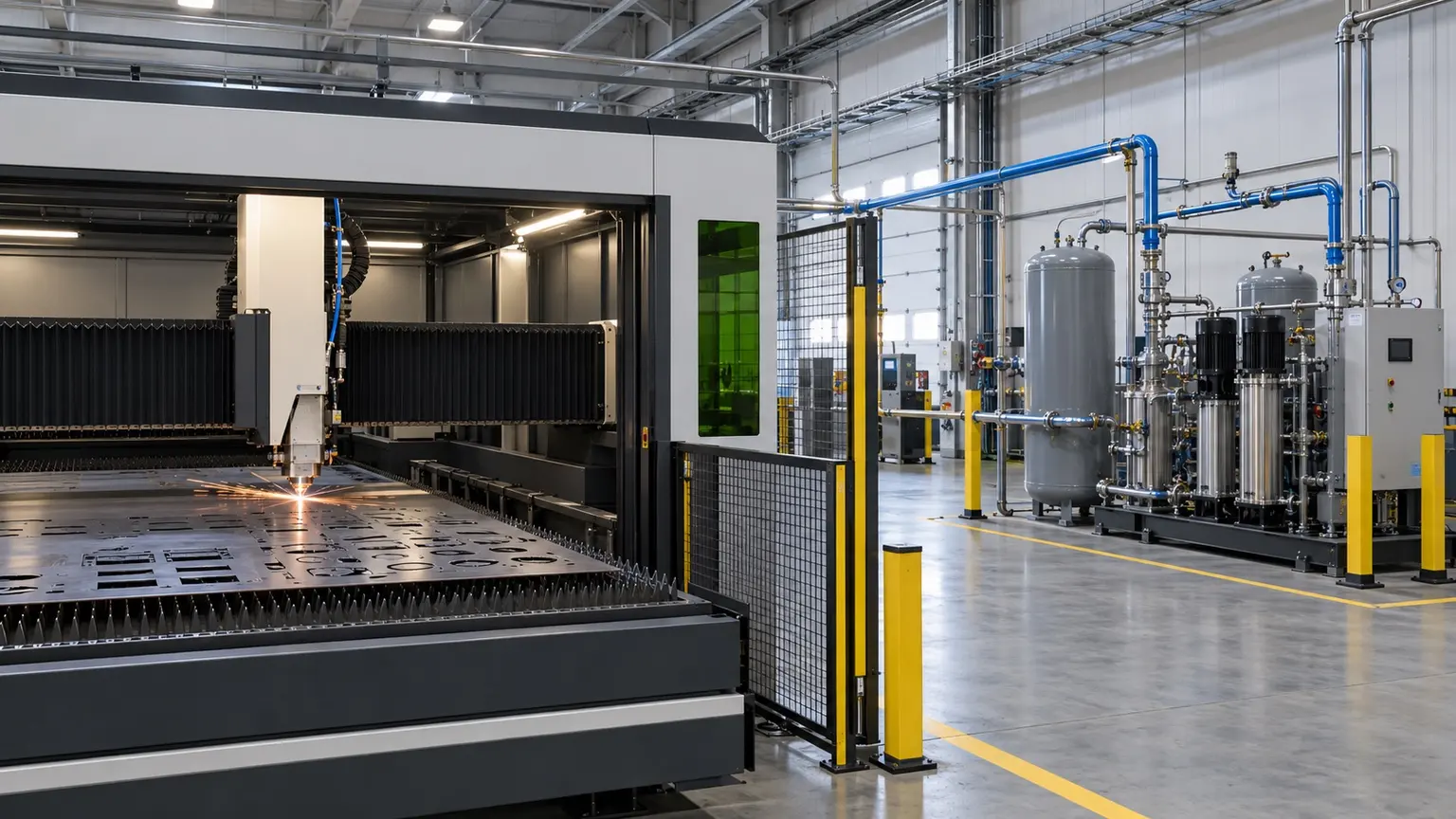
These are reference ranges from existing materials. Maximum flow and highest purity may not coincide. Confirm the model, feed conditions, dew-point basis and optional configuration in the project datasheet.
ENGINEERING NOTES
The following establishes a technical discussion framework. Final performance, scope, certification and acceptance criteria are defined in the agreed technical specification.
Maximum pressure alone is not enough. Provide continuous flow at each pressure level, peak duration, cycling frequency, allowable drop and recovery time.
ENGINEERING SCHEMATIC
First generate stable low-pressure nitrogen, then use the booster and high-pressure storage to cover continuous and peak demand.
Low-pressure generation followed by boosting and storage is usually more controllable than forcing the separation stage to deliver all pressure. Receiver volume and booster capacity require one dynamic demand model.
The high-pressure side requires suitable materials, valves, relief, drainage, temperature monitoring, vibration control and isolation, with testing and documentation to applicable codes.
Ambient temperature, altitude, dust or cleanliness, power, cooling, compressed air, space, logistics and local codes can change capacity, layout and scope.
List compression and treatment, generation or membranes, purification, boosting, storage, analysis, venting, controls, communications, piping and installation interfaces rather than comparing generator price alone.
Maintain continuity from factory testing and preservation through arrival inspection, SAT, training and operating trends. Contract and acceptance records govern final performance, responsibility and warranty.
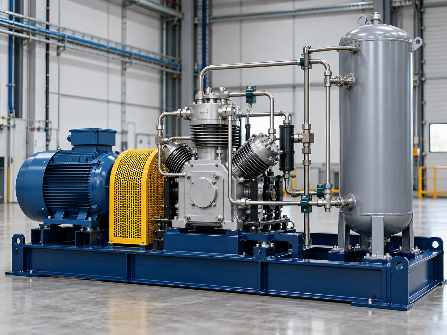
This image explains equipment configuration and engineering processes; it is not a customer-site or acceptance record.
EQUIPMENT & DELIVERY
The generator and booster have separate performance limits. Line losses and peaks affect pressure at the user. Low-pressure buffering, high-pressure storage, regulation and protection must be checked as one system, using the selected booster curve and project data.
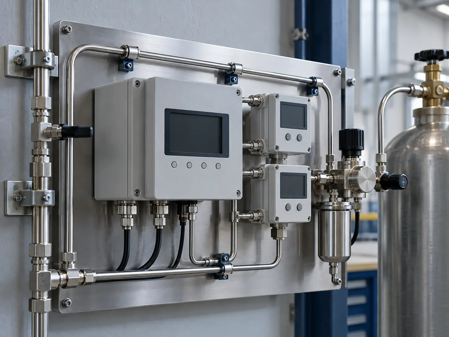
This image explains equipment configuration and engineering processes; it is not a customer-site or acceptance record.
EQUIPMENT & DELIVERY
Purity, residual oxygen and dew point are different specifications. Define the analyte, sampling location and pressure basis before choosing instruments, alarms and off-spec handling. The illustration explains the arrangement and contains no test readings.
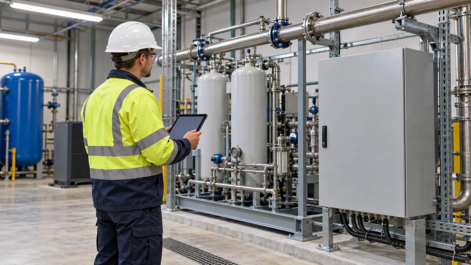
This image explains equipment configuration and engineering processes; it is not a customer-site or acceptance record.
EQUIPMENT & DELIVERY
After connection, check instruments, alarms, gas quality, pressure and off-spec handling under the agreed test plan, then complete training and handover. Acceptance depends on actual records; the screen shown here contains no performance data.
SYSTEM BOUNDARY
PAGE FAQ
Provide the process, average and peak flow, minimum purity, pressure, dew point, hours, environment, standards and target production date.
Standard modules may be the foundation, but train count, storage, treatment, controls and interfaces must be checked against the actual duty and site.
Write reference conditions, measurement method, sampling point, stabilisation, test duration, off-spec handling and responsibilities into the technical agreement.
CONTACT KEVIN
Send Kevin your application, location and the data you have. We will work through the next steps together.