Start with the load profile
Nameplate maximum flow is not enough. Average demand, peak duration, pressure fluctuation and acceptable turndown during faults determine train splitting, storage volume, redundancy and control logic.
HIGH-FLOW ENGINEERING
System-level engineering for mining, marine, chemical, new-energy and large continuous processes.
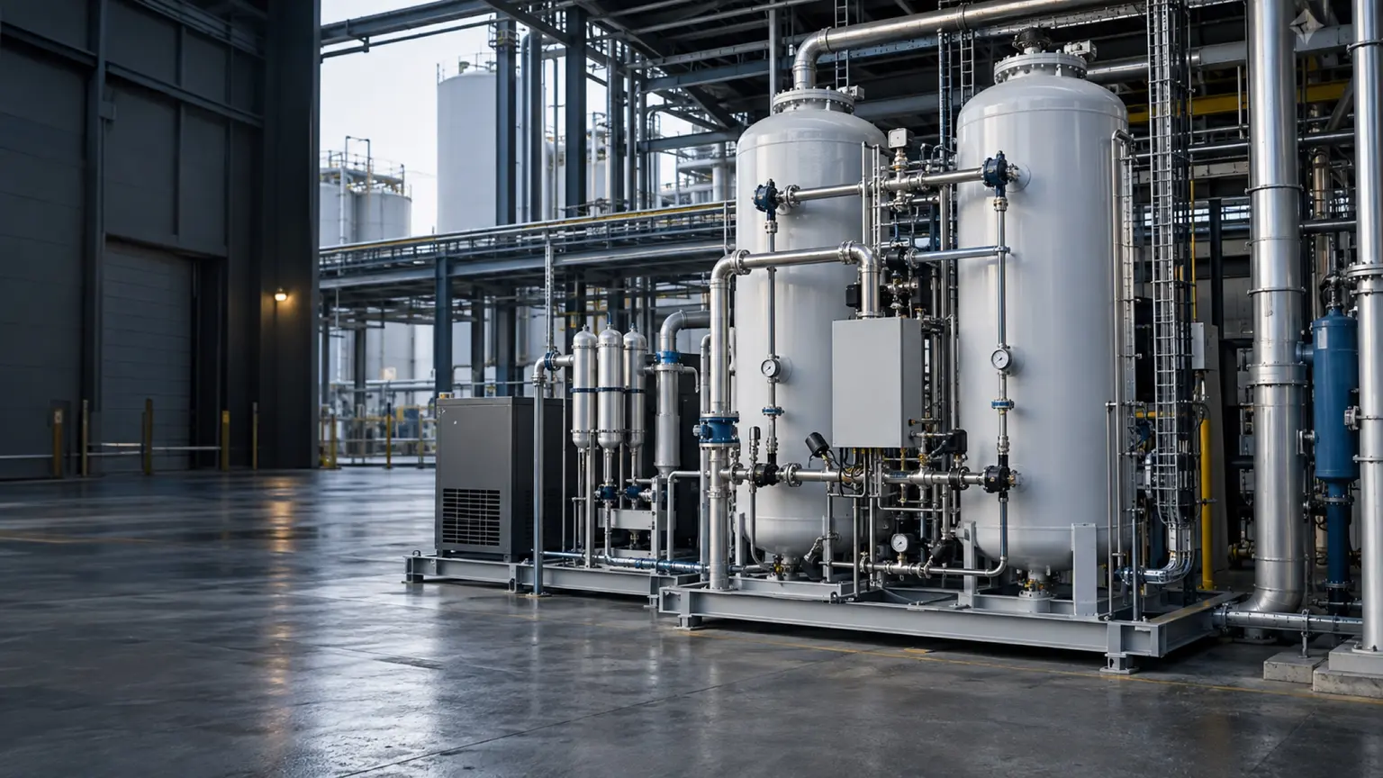
These are reference ranges from existing materials. Maximum flow and highest purity may not coincide. Confirm the model, feed conditions, dew-point basis and optional configuration in the project datasheet.
ENGINEERING NOTES
The following establishes a technical discussion framework. Final performance, scope, certification and acceptance criteria are defined in the agreed technical specification.
Nameplate maximum flow is not enough. Average demand, peak duration, pressure fluctuation and acceptable turndown during faults determine train splitting, storage volume, redundancy and control logic.
ENGINEERING SCHEMATIC
Average demand, peak duration and fault turndown determine duty trains, standby trains and header storage.
Scope can include compressor sequencing, parallel PSA or membrane trains, header balancing, online analysis, automatic venting, DCS communications, remote diagnostics, export packing and site interfaces.
Define reference conditions, flow measurement, purity sampling point, stabilisation time, pressure, dew point, energy boundary and test duration before manufacture so performance is repeatably verifiable.
High-flow systems may use parallel trains, phased expansion or N+1 architecture. Module count should reflect minimum load, maintenance windows, expansion schedule and single-failure consequence—not simply the sum of nameplate capacities.
The compressed-air plant is often the main energy and reliability boundary. Inlet pressure, cooling, drying, electrical capacity, drainage and heat rejection must be checked before the generator is finalised.
Large packages require early review of shipping dimensions, road and port limits, lifting weights, foundation loads, site assembly, line cleanliness and phased commissioning. Layout approval belongs before design freeze.
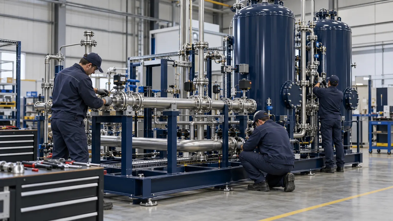
This image explains equipment configuration and engineering processes; it is not a customer-site or acceptance record.
EQUIPMENT & DELIVERY
Assembly follows controlled drawings and the equipment list. Review pipe supports, service access, electrical connections and instrumentation. Agree inspection items, test conditions and documents before manufacture. This manufacturing illustration is not evidence of a passed FAT.
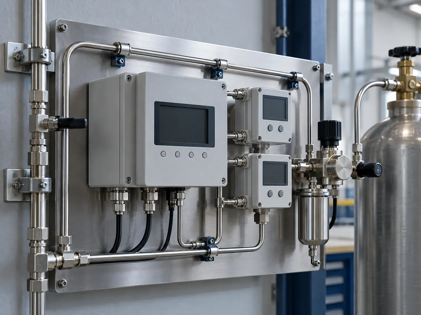
This image explains equipment configuration and engineering processes; it is not a customer-site or acceptance record.
EQUIPMENT & DELIVERY
Purity, residual oxygen and dew point are different specifications. Define the analyte, sampling location and pressure basis before choosing instruments, alarms and off-spec handling. The illustration explains the arrangement and contains no test readings.
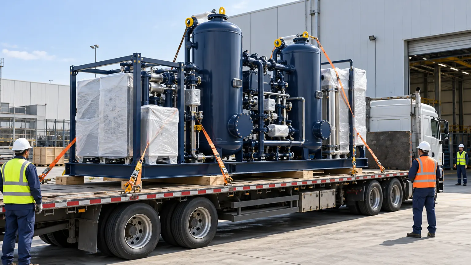
This image explains equipment configuration and engineering processes; it is not a customer-site or acceptance record.
EQUIPMENT & DELIVERY
Confirm the equipment list, preservation, lifting points, centre of gravity and transport limits before dispatch. The site prepares foundations, power, earthing, gas and drainage interfaces. Written responsibilities reduce rework. This image illustrates preparation, not a case shipment.
SYSTEM BOUNDARY
PAGE FAQ
Parallel trains can improve turndown, maintenance and redundancy, but add headers, controls and capital; the load profile determines the balance.
Use the peak shortfall, duration, allowable pressure drop, recovery time and backup strategy in a dynamic calculation.
Define the system boundary, reference temperature and pressure, flow and purity points, test duration and included auxiliaries.
CONTACT KEVIN
Send Kevin your application, location and the data you have. We will work through the next steps together.