Define impurities, not purity alone
Confirm allowable oxygen, moisture, oil, particles and other sensitive impurities together with sampling point and test method. The same nominal purity does not guarantee the same gas quality.
HIGH-PURITY NITROGEN
Generation, purification, analysis, storage and off-spec handling configured from the process residual-oxygen limit.
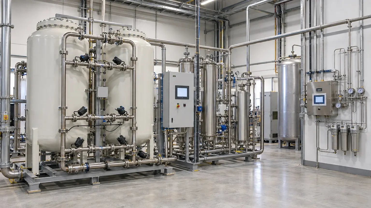
These are reference ranges from existing materials. Maximum flow and highest purity may not coincide. Confirm the model, feed conditions, dew-point basis and optional configuration in the project datasheet.
ENGINEERING NOTES
The following establishes a technical discussion framework. Final performance, scope, certification and acceptance criteria are defined in the agreed technical specification.
Confirm allowable oxygen, moisture, oil, particles and other sensitive impurities together with sampling point and test method. The same nominal purity does not guarantee the same gas quality.
ENGINEERING SCHEMATIC
Nominal purity is one metric; oxygen, moisture, oil, particles, sampling point and test method form one quality chain.
Depending on base generation and point-of-use specification, use direct PSA supply or add deoxygenation, drying, fine filtration, storage and online analysis. High purity is the result of the complete gas path, not a headline generator number.
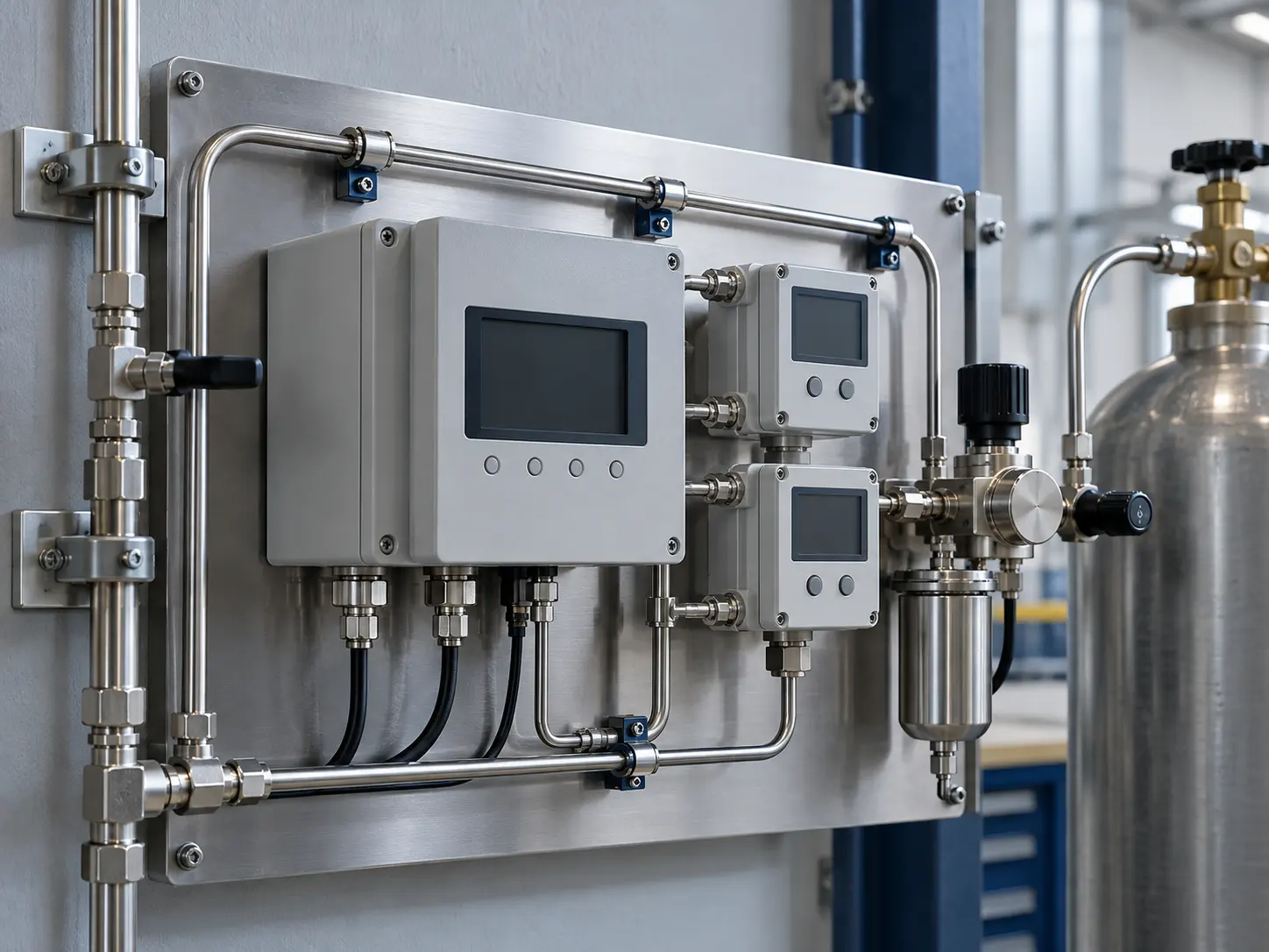
FAT and SAT should define analyser range, accuracy, calibration gas, stabilisation time, sample line and off-spec interlock, with trend records retained.
Ambient temperature, altitude, dust or cleanliness, power, cooling, compressed air, space, logistics and local codes can change capacity, layout and scope.
List compression and treatment, generation or membranes, purification, boosting, storage, analysis, venting, controls, communications, piping and installation interfaces rather than comparing generator price alone.
Maintain continuity from factory testing and preservation through arrival inspection, SAT, training and operating trends. Contract and acceptance records govern final performance, responsibility and warranty.
This image explains equipment configuration and engineering processes; it is not a customer-site or acceptance record.
EQUIPMENT & DELIVERY
Purity, residual oxygen and dew point are different specifications. Define the analyte, sampling location and pressure basis before choosing instruments, alarms and off-spec handling. The illustration explains the arrangement and contains no test readings.
This image explains equipment configuration and engineering processes; it is not a customer-site or acceptance record.
EQUIPMENT & DELIVERY
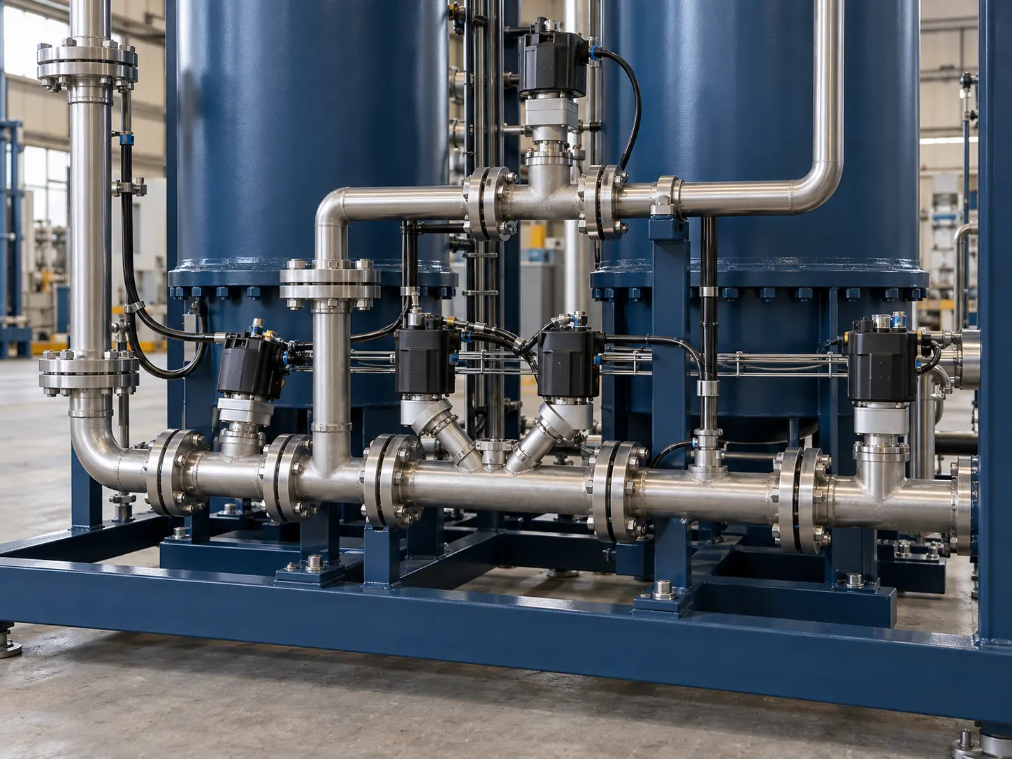
One tower adsorbs while the other regenerates. Valves sequence feed, pressure equalisation, delivery and exhaust. Buffering and off-spec handling must be assessed separately from the process demand, with access and spares planned for the valves.

This image explains equipment configuration and engineering processes; it is not a customer-site or acceptance record.
EQUIPMENT & DELIVERY
After connection, check instruments, alarms, gas quality, pressure and off-spec handling under the agreed test plan, then complete training and handover. Acceptance depends on actual records; the screen shown here contains no performance data.
SYSTEM BOUNDARY
PAGE FAQ
Provide the process, average and peak flow, minimum purity, pressure, dew point, hours, environment, standards and target production date.
Standard modules may be the foundation, but train count, storage, treatment, controls and interfaces must be checked against the actual duty and site.
Write reference conditions, measurement method, sampling point, stabilisation, test duration, off-spec handling and responsibilities into the technical agreement.
CONTACT KEVIN
Send Kevin your application, location and the data you have. We will work through the next steps together.